Many workshops built in the early years used concrete structures, and their crane beams were also concrete. After the secondary grouting layer of the track beam foundation of some factories was damaged or the embedded bolts broke, the concrete track beam and the steel rail could not be fixed, and the track shifted and fractured. universal. The problem of track fixing of concrete track beams can be solved by installing steel structure fasteners. I found some information on the Internet and shared it with everyone
At present, the construction of factory buildings adopts the method of steel structure welding construction. Steel structure construction has the advantages of short construction period and fast project progress. However, the production plants of some enterprises are still the 20th century brick-concrete structure factory buildings. The main load-bearing component of the lifting equipment is a concrete-cast reinforced concrete track beam. The track beam is prefabricated in advance. The crane track is positioned by bolt connection. As the service life increases, the embedded bolts of the concrete track beam are more likely to break. Generally, bridge cranes (double beam cranes) have poor track fastening and positioning. Therefore, it is necessary to take certain measures to achieve track positioning and fixation without replacing the concrete track beams.
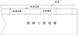
In the way of fixing the track on the concrete track beam , the generally adopted standard design form is shown in Figure 1.

Figure 1 Schematic diagram of the fixed connection of the track above the concrete track beam
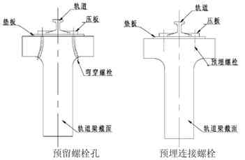
The fixed connection between the track beam and the track above the track is in the form of bolt connection (see Figure 1). The track pad is laid on the upper end of the track and the beam to adjust the error during the installation of the track beam. The lifting equipment runs above the track for a long time. Vibration, rail gnawing and other reasons cause the connecting bolt to break and the track displacement, which cannot guarantee the track installation accuracy at the initial stage of installation. There are two forms of connection and fixation between concrete track beam and track, as shown in Figure 2.

Figure 2 The connection and fixing form of concrete track beam and track
The main difference between the two forms of concrete track beam and track connection and fixation (see Figure 2) is that the bolts are set in different ways: one is to reserve bolt holes (bent holes) when concrete is poured, and the existing bent bolts are inserted during installation. Insert the bend hole and fix it; the other is the pre-embedded connecting bolt, which is fixed when the track is installed. After the on-site track connecting bolts are broken, the bent bolts are difficult to remove and penetrate, and the pre-embedded bolts cannot be processed on-site. The track beam needs to be replaced if it is thoroughly processed.
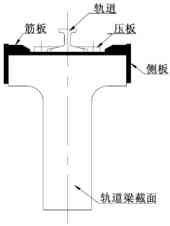
To try to realize the effective positioning and fixing of the track without replacing the track beam, the structural size of the track beam was measured first, and the analysis concluded that the track can be fixed by local steel structure fixing (see Figure 3).

Figure 3 Rail fixation scheme
After the rail bolt is broken, the rail mainly undergoes lateral displacement. In order to achieve accurate positioning of the rail, steel structure fasteners can be designed and manufactured, and the two-way lateral displacement of the rail can be controlled by the reinforced side plate on the side of the rail beam.
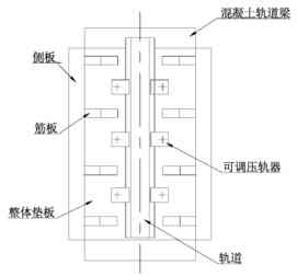
The steel structure fasteners were installed on the upper part of the driving track beam in the main span area of the 40t converter production line of the first steelmaking plant of Bayi Iron and Steel Co. The hidden dangers of track displacement and fracture.

Figure 4 Schematic diagram of production and installation of integral fasteners of steel structure
4. Precautions for the production and installation of steel structure fasteners
The reconstruction of the concrete crane beam is only a suggestion. If the plant is seriously damaged, the best way is to demolish and rebuild.
Contact our crane specialists
Send us a message and we will get back to you as soon as possible.